What is an Arduino?
INTRODUCTION
Arduino is an open-source platform used for building electronic projects. It consists of both a physical programmable circuit board, which is known as a Microcontroller and an IDE Arduino 1.8.2, which is used to write and upload computer code in to the physical board.
Unlike previous programmable circuit boards, the Arduino does not need a seperate piece of hardware (called a programmer) in order to load the new code onto the board - you can use the USB cable. Furthermore, the Arduino IDE uses a simplified version of C++ which makes it easier for us to learn to program.
 |
| Arduino UNO |
 |
| Arduino IDE (Version 1.8.2) |
WHAT'S ON THE BOARD?
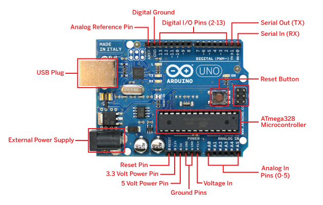
There are various Arduino Boards that can be used for different purposes. I've used the Arduino Uno board below, which is one of the most popular boards in the Arduino family and would be a great choice for a beginner.
- Power (USB Plug/ External Power Supply) : Arduino board requires a way to be connected to a available power source. Uno board can be powered from a USB cable from your computer or a wall power supply that is terminated in a barrel jack (Labeled: External Power Supply). The USB Plug is also used to load the code onto your Arduino board. Recommended voltage for most Arduino models is between 6 to 12 Volts.
- Ground Pins : Used to ground your circuit.
- 5 Volt Power Pin/ 3.3 Volt Power Pin : As it states, the 5V pin supplies 5 volts of power, and the 3.3V pin supplies 3.3 volts of power.
- Analog In Pins (0 - 5 on Arduino Uno ) : Theses pins can the read the signal from an analog sensor (like a temperature sensor) and convert it into a digital readable value.
- Digital I/ O Pins (2 - 13 on Arduino Uno ) : These pins can be used for both digital input and digital output. Ex : Button pressed (digit input), Powering a LED light (digital output).
- Pulse-Width Modulation : As you see in the above diagram, Digital I/O Pins (3, 5, 6, 9, 10, and 11 on the UNO) has a tilde (~). These pins act as digital pins, and are able to simulate analog outputs (Like blinking an LED in and out).
- Analog Reference Pin : Most of the times we leave the pin alone. Sometimes it is used to set an external reference voltage (between 0 and 5 Volts) as the upper limit for the analog input pins.
- Serial Out (TX) and Serial In (RX) : Uses TTL logic levels (5V or 3.3V depending on the board). Used to communicate between the Arduino board and a computer via USB.
- Reset Button : Pushing it will temporarily connect the reset pin to ground and reset any code that is loaded on the Arduino.
- ATmega328 Micro-controller : Think of it as the brain of our Arduino. Main IC on the Arduino is sightly different from board type, to board type. It is really important to know the IC type and the board type before loading a program in to the Arduino board.


very useful.. good stuff, thanks alot.
ReplyDeleteImportant details..
ReplyDeleteI was kind messed up sorting out the board. This helped a lot. Thank you ! :)
ReplyDelete